Prompt Collections
Master the art of industrial design generation with our curated gallery
Featured Concepts
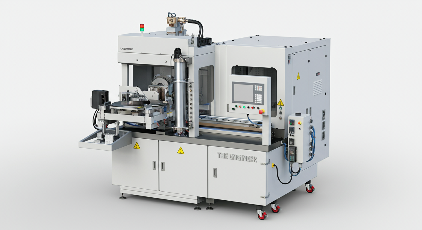
Industrial Automation Machine
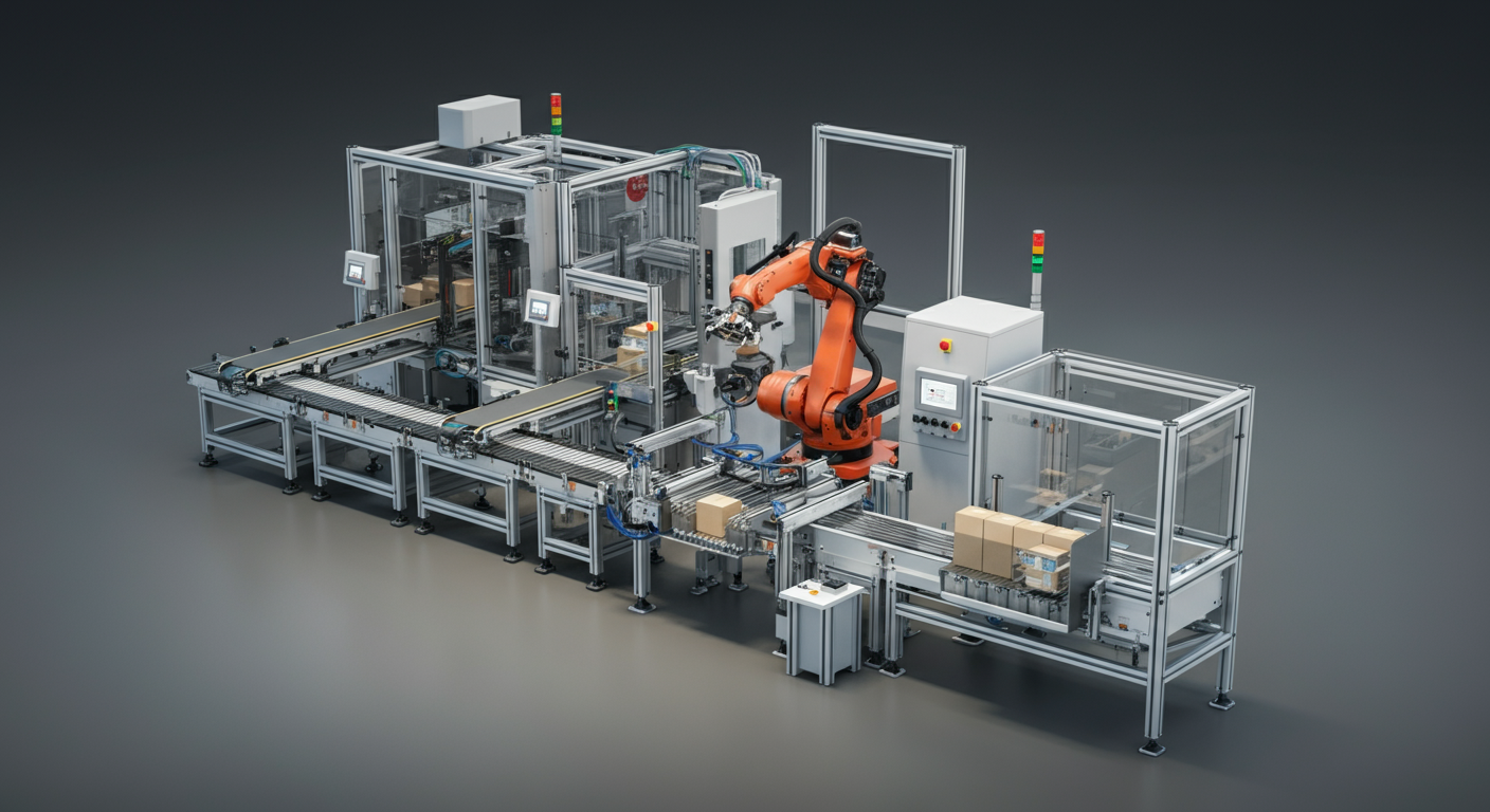
Logistics Automation Cell
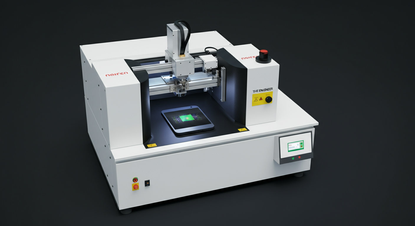
Vision Inspection Machine
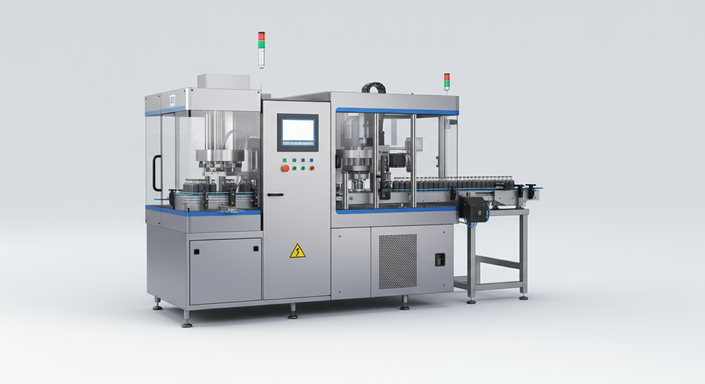
Industrial Capping Machine
Community Showcase
물티슈 캡 50층을 4열로 수직으로 쌓은 제품을 이송하는 컨베이어. 컨베이어 2개이고 1개당 50층 4열이고 2개니까 총 8열이야. 이걸 모터 하나로 돌릴거야
1. 외경 400mm, 내경 76mm, 길이600mm의 투명 필름 롤이 플라스틱 팔레트에 9개가 세로(z축)방향으로 세워져서 적재되어있음. 2. 다관절 로봇이 그리퍼 핸드를 통해 직접 클램핑하여 롤러스핀들에 넣는 레이아웃
A sophisticated technical 3D schematic of a robot loading system. Side and top view layout. A robot arm’s reach is indicated by semi-transparent red arcs. Cylindrical rollers are neatly arranged on a pallet. Minimalist design, blueprint aesthetic with glowing lines on a dark blue background, futuristic engineering concept.
로본 핸드
2500kg무게와 2500x2500x1500 크기의 직육면체 물체를 들어올리는 치구를 설계하려고 해. 케이블 와이어 4개를 안테나에 연결하고 와이어 두 가닥이 수평빔 양 끝에 연결해서 들어올리는 구조이고 수평빔 양 끝은 다시 두개의 와이어로 연결되어 반대편 와이어 끝이 마스터 링크에 연결됨. 마스터 링크는 공장의 크레인의 후크에 걸어 들어올리는 치구를 만들어줘
외경300mm, 내경 60mm, 길이500mm의 원통형 소재를 로봇이 내경을 그리핑해서 스핀들에 장차하는 시스템
A high-tech industrial automation cell featuring a yellow 6-axis articulated robot arm. The robot is positioned between a pallet filled with cylindrical rollers and a Roll-to-Roll spindle machine. The robot’s specialized mechanical gripper is clamping a heavy steel roller from a 3x3 grid pallet. Realistic factory environment with industrial lighting, safety fences, and a polished concrete floor. 8k resolution, ray-tracing, cinematic lighting, photorealistic.
다양한 공간에서 반복 설치·운영이 가능한 이동형 몰입 전시 플랫폼 구조도 modular exhibition frame system technical drawing profile
실리콘 튜브 입구에 동일한 실리콘 튜브를 접착할수있는 기계
프레스 기계 아니?
한국의 도로에 설치될 버스 정류소 만들어줘.
3종류의 제품을 잡을수 있는 6축로봇에 장착되는 그리퍼 jaw 구상해줘
초음파 커팅기
전동자율주행의자로 땅바닥에서 부터 높낮이 최저 10 mm 최고 600 mm 조절이 가능하고 승용차 트렁크에 수납이 가능하도록 3D로 도면을 만들어주세요. 최저 높이 땅바닥ㅇㅔ서 높이가 10 mm 맞추어야 됩니다.
항공기 정비를 위한 삼각잭, 안정적인 지지짐 유압장치
Formfactor 같은 반도체 장비 이미지
Industrial automation layout drawing in AutoCAD style, showing a 6-axis articulated industrial robot in both top view and side view. The robot is positioned next to a palletized roll arrangement, with multiple cylindrical rolls aligned in a grid pattern on a pallet sized 1100 x 1100 x 150 mm. A roll-to-roll spindle unit is placed above the robot working area. The robot working envelope is clearly illustrated using red circular and spiral arc lines, indicating rotational reach and motion range. Technical CAD drawing appearance: - Dark grid background - Thin white and yellow linework - Green outlines for products and pallets - Red arcs for robot working radius - Precise mechanical proportions - No shading, no realism, no textures Clean 2D vector-style engineering drawing, factory automation layout, robot cell layout design, industrial manufacturing planning diagram.
(X Concept AI: Project Design Master Data) 1. 기구학적 아키텍처 (Mechanical Architecture) AI가 3D 공간 내 부품 배치와 동적 간섭을 계산하기 위한 물리적 정의입니다. Main Chassis: 4-Station Rotary Index Table (Ø800mm Center). Station Layout (90° Interval): ST 10 (Loading/Unloading): 작업자 보호용 라이트 커튼(Keyence) 및 6-Bit 핀 센서 어레이 배치. ST 20 (Clinching): C-Frame 고정형 2ton 서보 프레스 유닛 및 로드셀 탑재. ST 30 (Riveting): 오비탈 리벳팅 헤드 및 2-Point 그리스 디스펜서 가변축 설계. ST 40 (Winding/Fixing): 테이블 하단 서보 권선기 + 상부 토크 암(Torque Arm) 너트러너 배치. Sub-Systems: 1.5m x 1.5m NVH 방음 부스(자동 도어), U자형 워크스테이션(OP 50), 성능 테스트 릭(OP 60). 2. 제품 및 지그 가변 사양 (Product & Jig Variants) 10종 이상의 모델 대응을 위한 가변성(Flexibility) 매개변수입니다. Target Models: 현대 BC4i (Safety/Normal, FR/RR), 기아 MQ4i (Safety/Normal, FR) - 각 LH/RH. Standard Interface (SMED): Mechanical: Ø12 다웰 핀(H7) 원점 2개소 + 제로포인트 클램핑 베이스. Electrical: Harting 24핀 멀티 커넥터 + 4포트 공압 퀵 커플러 통합 보드. Identification (Pin-Coding): 6-Bit Binary 코드 핀(지그 하단)을 통한 10종 모델 자동 판별 로직 적용. 3. 공정 제어 및 품질 로직 (Process & QC Logic) AI가 PLC I/O 맵과 시뮬레이션 시나리오를 생성하기 위한 작동 데이터입니다. Operational Sequence: (ST 10 인식) → (Index 90° 회전) → (ST 20/30/40 동시 구동) → (Data 저장) → (언로딩). Critical Thresholds (QC): Torque: 8~12Nm (±3% 공차), Load: Max 20kN (0.1kN 감지). Noise (NVH): 배경 소음 < 40dB, 주파수 분석 범위 20Hz ~ 20kHz (FFT). EOL: 작동 전류, 속도, 스트로크(BDC/TDC) 및 세이프티 모델 반전 기능 검증. 4. 표준 컴포넌트 라이브러리 (Standard Component Library) 3D 모델링 시 참조할 표준 브랜드 사양입니다. Controller: Allen Bradley PLC (EtherNet/IP). Actuators: SMC (Pneumatic), Hiwin (LM Guide), Mercury (Dispenser). Measurement: PCB Piezotronics (Microphone), Zebra (QR Printer), IR (Nut-runner). Materials: SS400(Frame), SKD11(Punch/Die, Heat-treated), Delrin(Jig Block). (AI 설계 수행 지시문 (Design Instructions)) Step 1: 10종 지그가 공통으로 결합되는 '표준 인터페이스 플레이트'와 '6-Bit 핀 센서 거치대'를 우선 설계하라. (pp. 2-3) Step 2: 인덱스 회전 시 상부 고정 유닛(프레스, 너트러너)과의 '동적 간섭'을 시뮬레이션하여 최적의 암(Arm) 길이를 산출하라. (pp. 6, 13) Step 3: 핀 코딩 조합에 따른 PLC I/O 할당표와 모델별 파라미터 자동 호출 로직을 생성하라. (pp. 4-5) Step 4: 방음 부스 내의 소음 분석(FFT) 데이터 서버 연동 및 QR 코드 출력 매칭 시스템을 구성하라. (pp. 18, 20)
Design a compact logistics automation cell within a 5m x 5m area using a small 6-axis articulated robot. The system includes an infeed conveyor belt delivering small boxes or containers, a top-mounted vision system that identifies object position and type, and a robot that picks up items using a vacuum gripper or mechanical fingers. The robot sorts and places the items onto output trays or an outfeed conveyor, based on QR code or RFID data. Include a white steel frame, linear conveyors, cameras, barcode readers, and a centralized controller box. The workspace layout must optimize efficiency and minimize robot idle time. Show cable management, sensor mounts, and a real-world factory floor texture. 'THE ENGINEER' visible on multiple sides of the machine.
밸트 컨베어
튜브 형태의 물체를 잡고 이동해서 튜브형태의 용기 안에 집어넣는 기계
전동자율주행의자로 높낮이 최저 10 mm 최고 600 mm 조절이 가능하도록 3D로 도면을 만들어주세요.
종이박스 펼쳐져있는것이 1500mm높이로 팔레트위에 쌓여져 있는데 이걸 산업용로봇을 활용해서 옴길생각이야, 그리퍼컨셉보여줘
1. 롤: 외경 400mm, 내경 76mm, 길이600mm 2. 적재 상태: 팔레트에 9개 세로(z축)방향 3*3배열(지관의 방향은 위를 향하고 있음) 3. 로봇 : 다축 로봇 4. 위치: 팔레트 왼쪽, 로봇 오른쪽 5. 동작 : 로봇 암으로 롤 내경 그립 후 상승된상태로 멈춤 6. 스핀들 : 로봇 오른쪽에 위치
키엔스 GP2-12k 센서를 활용한 접촉식 3포인트 두께 측정 설비를 만들고 싶어. 기본사양은 아래내용을 참고해서 만들어줘 1. 두께 측정기 1-1. 사용공정 1) Tape casting 後 Calendering 전/후 두께 측정 2) 완제품(소결 후 절단된 제품) 두께 측정 1-2. 제품 Size 1) Calendering 전/후 Size : Max 590*950, Min 제품의 폭 160 2) 완제품 size는 다양함. Min 예상 50*50 1-3. 장비 사양 1) Sensor : 접촉식. 초저압 측정기로 측정압은 0.5~1.0N 2) Sensor 분해능 : 1/1000 3) 동시 측정 Point 수 : 3Point. 단, Sensor 하나로 여러 Point 측정 가능 4) Total 측정 Point 수 : 변동 가능 5) 구동 : Sesor 축 구동 방식(제품이 Loading되는 Stage 구동 時 장비 Size가 커짐) 단, Sensor 축 구동 時 Data 반복성 확인 필요 6) Recipe : 규격화된 제품은 Recipe로 측정될 수 있도록 설계 7) 프로그램 : Data 처리는 PLC로 해도 무방하나 측정 Data는 산업용 컴퓨터 적용(엑셀 변환 가능)
전투용 드론 만들어줘
100제곱미터 1층 주택 방2개 1번방에는 화장실이 연결되어야 함 1번방은 남쪽향 부억과 거실은 오픈형태 평면도
프레스 기계 아니? 플라이휠이 적용된 4주식 5링크 프레스 그려줄 수 있니?
(X Concept AI: Project Design Master Data) 1. 기구학적 아키텍처 (Mechanical Architecture) AI가 3D 공간 내 부품 배치와 동적 간섭을 계산하기 위한 물리적 정의입니다. Main Chassis: 4-Station Rotary Index Table (Ø800mm Center). Station Layout (90° Interval): ST 10 (Loading/Unloading): 작업자 보호용 라이트 커튼(Keyence) 및 6-Bit 핀 센서 어레이 배치. ST 20 (Clinching): C-Frame 고정형 2ton 서보 프레스 유닛 및 로드셀 탑재. ST 30 (Riveting): 오비탈 리벳팅 헤드 및 2-Point 그리스 디스펜서 가변축 설계. ST 40 (Winding/Fixing): 테이블 하단 서보 권선기 + 상부 토크 암(Torque Arm) 너트러너 배치. Sub-Systems: 1.5m x 1.5m NVH 방음 부스(자동 도어), U자형 워크스테이션(OP 50), 성능 테스트 릭(OP 60). 2. 제품 및 지그 가변 사양 (Product & Jig Variants) 10종 이상의 모델 대응을 위한 가변성(Flexibility) 매개변수입니다. Target Models: 현대 BC4i (Safety/Normal, FR/RR), 기아 MQ4i (Safety/Normal, FR) - 각 LH/RH. Standard Interface (SMED): Mechanical: Ø12 다웰 핀(H7) 원점 2개소 + 제로포인트 클램핑 베이스. Electrical: Harting 24핀 멀티 커넥터 + 4포트 공압 퀵 커플러 통합 보드. Identification (Pin-Coding): 6-Bit Binary 코드 핀(지그 하단)을 통한 10종 모델 자동 판별 로직 적용. 3. 공정 제어 및 품질 로직 (Process & QC Logic) AI가 PLC I/O 맵과 시뮬레이션 시나리오를 생성하기 위한 작동 데이터입니다. Operational Sequence: (ST 10 인식) → (Index 90° 회전) → (ST 20/30/40 동시 구동) → (Data 저장) → (언로딩). Critical Thresholds (QC): Torque: 8~12Nm (±3% 공차), Load: Max 20kN (0.1kN 감지). Noise (NVH): 배경 소음 < 40dB, 주파수 분석 범위 20Hz ~ 20kHz (FFT). EOL: 작동 전류, 속도, 스트로크(BDC/TDC) 및 세이프티 모델 반전 기능 검증. 4. 표준 컴포넌트 라이브러리 (Standard Component Library) 3D 모델링 시 참조할 표준 브랜드 사양입니다. Controller: Allen Bradley PLC (EtherNet/IP). Actuators: SMC (Pneumatic), Hiwin (LM Guide), Mercury (Dispenser). Measurement: PCB Piezotronics (Microphone), Zebra (QR Printer), IR (Nut-runner). Materials: SS400(Frame), SKD11(Punch/Die, Heat-treated), Delrin(Jig Block). (AI 설계 수행 지시문 (Design Instructions)) Step 1: 10종 지그가 공통으로 결합되는 '표준 인터페이스 플레이트'와 '6-Bit 핀 센서 거치대'를 우선 설계하라. (pp. 2-3) Step 2: 인덱스 회전 시 상부 고정 유닛(프레스, 너트러너)과의 '동적 간섭'을 시뮬레이션하여 최적의 암(Arm) 길이를 산출하라. (pp. 6, 13) Step 3: 핀 코딩 조합에 따른 PLC I/O 할당표와 모델별 파라미터 자동 호출 로직을 생성하라. (pp. 4-5) Step 4: 방음 부스 내의 소음 분석(FFT) 데이터 서버 연동 및 QR 코드 출력 매칭 시스템을 구성하라. (pp. 18, 20) 작업자 넣어 주고, 내부를 볼 수 있도록 해줘
산업용 AOI 검사 설비 설계: 1.하부: 대형 석정반(Granite Base) 위에 6G 패널용 X축 스테이지 설치. 2.프레임: 석정반 외곽에 4개의 기둥(Post)과 그 위를 연결하는 2줄의 고정형 Y축 롱 브릿지. 3.구동부 (중요): Y축 리니어 가이드는 브릿지의 **안쪽 측면(Side-mounted)**에 설치됨. 4.유닛 구성: 한 줄의 Y축 가이드에 2개의 독립적인 'Small X-Bridge' 유닛이 매달려 있음. (Y축 가이드 몿터 총 4개 / Small X Bridge 2개) 5.세부 사항: 각 Small X-Bridge 위에는 110mm 스트로크의 리니어 로봇과 1개의 Review 광학계가 장착됨. 케이블베어와 복합적인 XY축 이동 구조가 보이는 등각 투영도(Isometric View).
사람을 따라다니는 적재가 가능한 로봇(짐차)를 만들껀데 구동부 바퀴는 두개(뒷바퀴) 앞바퀴는 캐스터를 쓸거야. 구동바디프레임에 바퀴가 달리는형태이고 앞부분에는 범퍼센서를 달아서 최악의 상황에 대비할거임. 페이로드는 300KG이고. 적재 상판과 바디프레임은 분해가 가능했으면 좋겠어. 그리고 적재상판에는 수동 컨트롤러가 달릴예정이야, 물론 라이다 센서를 이용해서 자동기능도 넣을 예정이고. 근데 컨트롤러가 달린 구조는 접이식어있으면 좋겠어 <참고프롬프트> 저상형 자율 물류 이동 로봇 플랫폼의 CAD 스타일 3D 렌더링. 직사각형 상판은 알루미늄 프로파일 프레임과 검은색 플레이트로 구성되어 있으며, 후방에는 러기드 타이어가 장착된 듀얼 구동 휠, 전방에는 2개의 스위블 캐스터 휠이 있다. 전면 좌측에는 조이스틱이 장착된 수직 기둥이 설치되어 있다. 하부는 용접된 박스형 강철 프레임 구조이며, 4개의 수직 지지 기둥이 상판과 하부 베이스를 연결한다. 허브 모터, 보강 브라켓, 프레임 구조가 보이는 기계적 디테일이 강조된 산업용 설계 렌더링. 스튜디오 배경, 부드러운 그림자, 전면에 반투명 노란색 원형 오버레이가 표시되어 회전 반경 또는 감지 영역을 표현.
컴퓨터 모뎀을 만들어줘
컨베이어
컨베이어를 그릴겁니다.벨트 타입이고 벨트의 폭은 15미리 컨베이어 폭 조절 가능 하도록 속도는 6m/min 모터는 서보 모터 사용 꼭 폭이 조절 가능하도록 컴팩트 하게 설계 해주세요
Design an automotive body welding assembly line inside a large industrial production hall using multiple heavy-duty 6-axis articulated welding robots arranged symmetrically on both sides of a central conveyor. The system includes a car body chassis fixture moving along a rail-guided conveyor, robotic arms performing synchronized spot welding and structural joining, and protective safety fences with transparent green panels. Overhead cable trays, steel support beams, and industrial lighting are mounted on the ceiling. Include robot controllers, welding power units, cooling lines, and automated tool changers. The workspace layout must emphasize high-throughput automotive manufacturing efficiency and precise alignment of the chassis during welding. Show realistic cable routing, hydraulic lines, safety sensors, and factory floor markings with an industrial metal texture. A busy, high-tech automotive factory atmosphere with depth and perspective is required. “THE ENGINEER” visible on multiple structural surfaces of the production cell.
DC-DC 컨버터는 1. 100kW, 2. 200kW, 3. 500kW 파워모듈(충전)은 1. 120kW, 2. 200kW, 3. 520kW 조건 : 1)냉각수 inlet 라인이 파란색, outlet 라인이 빨간색 2)기존 제품 크기 유지한 상태 순번 1,2,3,4,5,6,용량별 모델에 대한 , 각각 이미지 6개로 생성해줘
전동자율주행의자로 높낮이 최저 10 mm 최고 600 mm 조절이 가능하도록 3D로 도면을 만들어주세요.
항공기 삼각잭
롤러는 파렛트에 적재되어있으며 다관절 로봇이 그리퍼 핸드를 통해 직접 클램핑하여 롤러스핀들에 넣는 레이아웃 외경 400mm, 내경 76mm, 길이600mm의 투명 필름 롤이 플라스틱 팔레트에 9개가 길비방향으로 세워져서 적재되어있음. 로봇이 내경을 클램프하여 반대쪽 내경을 스핀들에 꽂아주는 시스템.
I want to build Flower garland machine
원형 형태의 물체를 원형 띠형태의 용기 안에 집어넣는 기계
100제곱미터 주택 방2개 1번방에는 화장실이 연결되어야 함 부억과 거실은 오픈형태
1. 롤: 외경 400mm, 내경 76mm, 길이600mm 2. 적재 상태: 3*3배열, 9개 길이방향, 파렛트 3. 로봇 : 다축 로봇 4. 위치: 팔레트 왼쪽, 로봇 오른쪽 5. 동작 : 로봇 암으로 롤 내경 그립 후 상승된상태로 멈춤 6. 스핀들 : 로봇 오른쪽에 위치
이동형 미디어 아트 전시(빔프로젝터 투사형) 부스를 모듈러로 만들어줘 15인 정도의 인원이 관람 할 수 있어야 함. 모듈간 연결 조인트 부분을 통해 구부러지는 구조로 평면적 미디어 아트 전시 구조부터 라운드형 구조까지 유동적으로 설치가 가능한 모듈러 미디어 아트 전시 부스를 만들고 싶어
전투용 드론 만들어줘
프레스 기계 아니?
전동자율주행의자로 땅바닥에서 부터 높낮이 최저 10 mm 최고 600 mm 조절이 가능하고 승용차 트렁크에 수납이 가능하도록 3D로 도면을 만들어주세요.
파우치배터리 이물 및 Gap 검사기를 만드는데 파우치 폭은 500mm, 높이는 110mm, 두께는 15mm 이며 이물검사를 위해 컨베이터 벨트 위에 배터리를 놓고 회전하는 벨트 사이에 디텍터가 위치한다. 롯봇이 벨트위에 배터리 셀을 두개 씩 400mm 피치로 올려 놓으면, In conveyor 가 장비로 가지고 들어가면서 Work Conveyor로 올라 타고 , 실린더로 얼라인을 하고 검사 위치로 이동한다. 검사위치에서 X-ray가 셀의 반만 찍고, 반은 다음 위치에서 다른 X-ray 가 찍는다.다시 한피치 이동한 후 out Conveyor로 이동하고이동된 셀은 로봇이 두개씩 가져간다 이러한 컨셉을 만들어 주세요커버 없이 일단 물류 컨셉을 만들어 주세요
1. 롤: 외경 400mm, 내경 76mm, 길이600mm 2. 적재 상태: 팔레트에 9개 세로(z축)방향 3*3배열 3. 로봇 : 다축 로봇 4. 위치: 팔레트 왼쪽, 로봇 오른쪽 5. 동작 : 로봇 암으로 롤 내경 그립 후 상승된상태로 멈춤 6. 스핀들 : 로봇 오른쪽에 위치
컴퓨터를 만들어줘
battery chiller
밸트 컨베어
100제곱미터 1층 주택 방2개 1번방에는 화장실이 연결되어야 함 부억과 거실은 오픈형태 평면도
1. 롤: 외경 400mm, 내경 76mm, 길이600mm 2. 적재 상태: 팔레트에 9개 세로(z축)방향 3*3배열(지관의 방향은 위를 향하고 있음) 3. 로봇 : 다축 로봇 4. 위치: 팔레트 왼쪽, 로봇 오른쪽 5. 동작 : 로봇 암으로 롤 내경 그립 후 상승된상태로 멈춤 6. 스핀들 : 로봇 오른쪽에 위치
청소용 드론 만들어줘
Subject: A wide, high-resolution architectural collage image divided into three vertical panels (Triptych). [Left Panel - Square Mode]: A massive (10m x 10m) open-plan aluminum structure in a Gymnasium. A class of 15 children are freely running around inside, chasing digital letters projected on the floor and walls. The space is huge, allowing full-body interaction without crowding. [Center Panel - Round Mode]: A giant Concave (Inward-curving) panorama wall (Diameter 12m). It wraps around the viewers like a C-shaped cinema. 15 visitors are standing in the center, looking up at the "Starry Night of Hangeul" projected on the curved walls. They are interacting by waving hands at the screen, with ample distance between each person. [Right Panel - Atypical Mode]: A long, flowing media wall (15m length) winding through a convention center hallway. Crowds of people are walking *along* the wall, and the digital Hangeul characters follow their movement like a shadow. [Style]: Uniform photorealistic rendering, 8k resolution, Ultra-Wide Angle Lens (14mm) used to exaggerate space, bright and active atmosphere.
빔 아래에 있는 두 개의 노란색 호이스링은 지워주고 맨 위에 노란색 마스터링크는 장홀 모양의 고리형태로 바꿔줘. 사슬모양의 줄은 케이블와이어 형태로 바꿔지고 수평빔은 원기둥형태로 바꿔줘
네, 알겠습니다! 위에서 분석했던 프롬프트 작성의 핵심 원리들을 바탕으로, 페라리와 같은 고성능 차량을 도색하는 기계에 대한 상세하고 기술적인 영어 프롬프트를 작성해 드리겠습니다. AI가 실제 공장에서 볼 수 있는 듯한 사실적인 도색 로봇 시스템을 생성하도록 유도할 것입니다. Here's an English prompt for an AI image generation model, designed to create a detailed and realistic painting machine for a high-performance sports car like a Ferrari: Image Title Suggestion: High-Precision Automotive Painting Robot Cell Prompt: "A highly detailed, photorealistic render of an advanced robotic painting cell designed for luxury sports cars. The scene is set inside a pristine, brightly lit automotive factory environment, featuring clean white walls and polished epoxy flooring with clear safety markings (e.g., yellow and black striped lines). The central focus is a multi-axis industrial painting robot (e.g., a 7-axis anthropomorphic robot arm), specifically designed for automotive applications. The robot arm has a smooth, sleek, and durable protective casing, possibly in a metallic silver, dark gray, or even a subtle red accent to complement the car. All cables and pneumatic lines are neatly managed within energy chains running along the robot's arm, emphasizing precision and safety. The robot's end effector is a specialized, high-volume, low-pressure (HVLP) spray gun system, integrated with advanced atomization technology. Visible details include fine nozzles, possibly small sensor arrays for paint thickness measurement, and integrated air lines. The robot is actively painting a sleek, aerodynamic sports car chassis (e.g., a Ferrari-esque body-in-white or a primed body shell) positioned precisely on a rotating turntable or a conveyor jig. The car body is shown in a specific stage of painting, with a freshly applied, wet, and glossy rich metallic red paint finish on certain panels, while other areas are still in primer or waiting for the next coat. The paint mist and fine droplets should be subtly visible around the spray nozzle, illuminated by the bright factory lights. In the background, there are elements of a cleanroom environment: HEPA filters on the ceiling, air circulation vents, and possibly a glass viewing panel for technicians. Focus on the sophisticated mechanical design, the fluid movement implied by the robotic arm's posture, and the high-tech precision of the painting process. Avoid any human presence. Style: Technical illustration, industrial photography, hyperrealistic rendering, 8k resolution, cinematic lighting emphasizing reflections on the wet paint and metallic surfaces, engineering blueprint aesthetic where appropriate, but overall a vivid and operational scene. No futuristic or cartoonish elements. The design should convey robust industrial engineering."
회전식 누룽지 기계를 만들어줘 팔각형 구조로 되어있고 누룽지 금형에 불린쌀을 일정량 올려주면 한개의 각만큼 회전하면서 닫혀있던 몰드에 있는 완성된 누룽지를 사람이 꺼내주고 이어서 금형몰드에 불린쌀을 넣어주고 연속으로 한개의 각만큼 회전하며 몰드는 닫히는 구조야
등각투영도로 만들어줘
사람을 따라다니는 적재가 가능한 로봇(짐차)를 만들껀데 구동부 바퀴는 두개(뒷바퀴) 앞바퀴는 캐스터를 쓸거야. 구동바디프레임에 바퀴가 달리는형태이고 앞부분에는 범퍼센서를 달아서 최악의 상황에 대비할거임. 페이로드는 300KG이고. 적재 상판과 바디프레임은 분해가 가능했으면 좋겠어. 그리고 적재상판에는 수동 컨트롤러가 달릴예정이야, 물론 라이다 센서를 이용해서 자동기능도 넣을 예정이고. 근데 컨트롤러가 달린 구조는 접이식어있으면 좋겠어 <참고프롬프트> 저상형 자율 물류 이동 로봇 플랫폼의 CAD 스타일 3D 렌더링. 직사각형 상판은 알루미늄 프로파일 프레임과 검은색 플레이트로 구성되어 있으며, 후방에는 러기드 타이어가 장착된 듀얼 구동 휠, 전방에는 2개의 스위블 캐스터 휠이 있다. 전면 좌측에는 조이스틱이 장착된 수직 기둥이 설치되어 있다. 하부는 용접된 박스형 강철 프레임 구조이며, 4개의 수직 지지 기둥이 상판과 하부 베이스를 연결한다. 허브 모터, 보강 브라켓, 프레임 구조가 보이는 기계적 디테일이 강조된 산업용 설계 렌더링. 스튜디오 배경, 부드러운 그림자, 전면에 반투명 노란색 원형 오버레이가 표시되어 회전 반경 또는 감지 영역을 표현.
Probestation
battery chiller
컨베이어
튜브 형태의 물체를 튜브형태의 용기 안에 집어넣는 기계
ultra realistic industrial automation scene, composition: pallet on the left third, single 6-axis robot on the right third, robot using a heavy-duty load-rated cantilever internal expanding mandrel, mandrel inserted into the 76mm inner core, robot lifting the roll from the side, roll fully suspended in air, weight supported only by the mandrel, true cantilever configuration, opposite side unsupported, pallet holding exactly nine transparent polymer film rolls in a perfectly aligned 3x3 grid, correct industrial scale, engineering visualization style, clean white studio background roll touching pallet, partially supported, dual support shaft, floor contact
청소용 드론 만들어줘
망고 스마트팩토리로 컨셉안 설비로 구성해줘
화낙 6축로봇
군사용 드론 만들어줘
WHITE_BACKGROUND_ONLY studio-style industrial 3D render. On the left side, a pallet holds nine transparent film rolls arranged in a 3 by 3 grid. Each roll is standing vertically along the Z-axis, with the hollow paper core facing upward. Roll specifications: - outer diameter: 400 mm - inner diameter: 76 mm - length: 600 mm - transparent plastic film material On the right side of the pallet, a multi-axis industrial robot is installed. The robot arm uses an internal expanding gripper to clamp the inner diameter (Ø76 mm) of one roll. The robot has lifted the roll upward and is holding it suspended in the air, paused after gripping, before insertion. A roller spindle unit is positioned to the right side of the robot, aligned for the next loading step. Rendering style: - clean white studio background only - industrial equipment visualization - realistic but clean materials (painted steel robot, plastic pallet, transparent film) - precise mechanical geometry - real-world scale proportions - CAD-inspired structured design, fully rendered 3D - professional product and automation system visual - no environment, no floor, no walls Industrial robotic roll handling system visualization.
Industrial automation layout drawing in AutoCAD style, showing a 6-axis articulated industrial robot in both top view and side view. The robot is positioned next to a palletized roll arrangement, with multiple cylindrical rolls aligned in a grid pattern on a pallet sized 1100 x 1100 x 150 mm. A roll-to-roll spindle unit is placed above the robot working area. The robot working envelope is clearly illustrated using red circular and spiral arc lines, indicating rotational reach and motion range. Technical CAD drawing appearance: - Dark grid background - Thin white and yellow linework - Green outlines for products and pallets - Red arcs for robot working radius - Precise mechanical proportions - No shading, no realism, no textures Clean 2D vector-style engineering drawing, factory automation layout, robot cell layout design, industrial manufacturing planning diagram. photorealistic, 3D render, real factory photo, people, textures, materials, lighting effects, shadows, blur, noise, hand-drawn, sketch, cartoon, artistic illustration, isometric view, perspective distortion
가장 대표적인 컴퓨터 CPU의 구조를 그려줘
유압 프레스 만들어줘
Design an industrial automation machine that handles tubular plastic film and inserts it into a tubular container, then applies a secondary pressing operation. Process description: The machine grips the tubular plastic film from the top using a non-damaging gripping mechanism. The film is guided vertically and inserted into a cylindrical container while maintaining its tubular shape. After insertion, a secondary pressing mechanism compresses the film downward to fully seat it inside the container. The process must avoid tearing, wrinkling, or collapsing the tube. Design requirements: The film is flexible and thin, so no excessive clamping force is allowed. The container is also tubular, and alignment accuracy is critical. The pressing action should be controlled (force- or stroke-limited). Continuous or semi-automatic operation is preferred. Please provide: Overall machine structure and layout Gripping mechanism concept Insertion and guiding method Secondary pressing mechanism design Recommended actuators (pneumatic / electric / servo) Sensors required for position and error detection Optional improvements for stability and repeatability
프레스 기계 아니? 플라이휠이 적용된 4주식 5링크 프레스 그려줄 수 있니? 2000톤 트랜스퍼 프레스 이고, 볼스터 크기는 4500x2500mm 슬라이드 스트로크는 1100mm 500kW AC 모터가 벨트로 연결된 플라이휠을 구동하여 5링크 메카니즘에 연결된 슬라이드를 구동하는 방식이야
1. 롤: 외경 400mm, 내경 76mm, 길이600mm 2. 적재 상태: 팔레트에 9개 세로(z축)방향 3*3배열(지관의 방향은 위를 향하고 있음) 3. 로봇 : 다축 로봇 4. 위치: 팔레트 왼쪽, 로봇 오른쪽 5. 동작 : 로봇 암으로 롤 내경 그립 후 상승된상태로 멈춤 6. 스핀들 : 로봇 오른쪽에 위치
1. 롤: 외경 400mm, 내경 76mm, 길이600mm 2. 적재 상태: 팔레트에 9개 세로(z축)방향 3*3배열 3. 로봇 : 다축 로봇 4. 위치: 팔레트 왼쪽, 로봇 오른쪽 5. 동작 : 로봇 암으로 롤 내경 그립 후 상승된상태로 멈춤 6. 스핀들 : 로봇 오른쪽에 위치
Prompt: "A highly detailed, engineering-focused 3D render of a 6-axis industrial articulated robot arm, inspired by the Hyundai Robotics HA/HH series. Main Structure: The robot features a robust, industrial-grade body with a distinctive vibrant orange powder-coated finish. The structure consists of a solid circular base, a thick lower arm (link 1), and a slender upper arm with integrated heavy-duty servos and high-precision joints. External black flexible cable conduits (energy chains) are neatly routed along the 'Link 2' and 'Link 3' joints, secured by black industrial clamps. Mechanical Details: Show clear mechanical joints for Swivel (S), Forward/Backward (H), Up/Down (V), Rotation (R2), Bending (B), and Rotation (R1). The wrist section is compact and features an ISO-standard mounting flange for end-effectors. The surfaces should have a semi-gloss texture reflecting studio lights. Visible bolt patterns on joint housings and a small metallic manufacturer’s plate on the base add to the realism. Environment & Setup: The robot is mounted on a clean, light-gray industrial concrete floor in a 'Floor-mounted' position. The background is a minimalist, professional studio setting with neutral gray tones to emphasize the robot's form. Technical Style: Photorealistic CAD rendering style, 8k resolution, sharp focus on mechanical articulations, cinematic studio lighting with soft shadows. No human figures. The overall aesthetic should be functional, realistic, and commercially ready, avoiding any sci-fi or 'toy-like' appearance. Key focus on the ratio of the arm length and the heavy-duty industrial build quality."
청소용 드론 만들어줘
프레스 기계 아니? 흠... 지금 보여 준 것이 프레스 기계 이미지?
리프트크기가 폭 2미터 길이 4미터 높이 6미터을 이용한 4톤용량의 호이스트 크레인
1. 롤: 외경 400mm, 내경 76mm, 길이600mm 2. 적재 상태: 팔레트에 9개 세로(z축)방향 3*3배열(지관의 방향은 위를 향하고 있음) 3. 로봇 : 다축 로봇 4. 위치: 팔레트 왼쪽, 로봇 오른쪽 5. 동작 : 로봇 암으로 롤 내경 그립 후 상승된상태로 멈춤 6. 스핀들 : 로봇 오른쪽에 위치
100제곱미터 1층 주택 방2개 1번방에는 화장실이 연결되어야 함 부억과 거실은 오픈형태 평면도
회전식 누룽지 기계를 만들어줘 팔각형 구조로 되어있고 누룽지 금형에 불린쌀을 일정량 올려주면 한개의 각만큼 회전하면서 닫혀있던 몰드에 있는 완성된 누룽지를 사람이 꺼내주고 이어서 금형몰드에 불린쌀을 넣어주고 연속으로 한개의 각만큼 회전하며 몰드는 닫히는 구조야
실리콘 튜브 입구에 동일한 실리콘 튜브를 접착할수있는 기계
한국에서 인기좋은 화목난로 만들어줘
6축로봇과 박스 이송용 라운드 밸트 컨베어 구상해주세요
High-End RGB Gaming PC Desktop: Photorealistic 3D Product Rendering Prompt Role: You are an expert 3D product visualization artist. Create a photorealistic 3D render of a high-performance custom gaming PC tower based on the reference image. 1. Macro Structure & Material Specifications (Standard & Material): Chassis Standard: A mid-tower ATX form factor PC case. Primary Materials: The main body is constructed from matte black powder-coated SPCC steel. The left side panel is a full-sized sheet of tinted tempered glass. The front panel features a fine metal mesh grille set within a black ABS plastic frame to maximize airflow. Internal Components: Visible internal components include a black PCB ATX motherboard, a large graphics card with a metal backplate and plastic shroud showing "GEFORCE RTX" and "ZOTAC GAMING" logos, and a tower-style CPU air cooler with an aluminum heatsink and plastic RGB fan. 2. Mechanical Constraints & Cooling System (Mechanical Constraints): Active Cooling: Explicitly model the cooling system in operation. Front Intake: Three (3) 120mm addressable RGB (ARGB) LED fans mounted behind the front mesh panel, actively rotating. Rear Exhaust: One (1) 120mm ARGB LED fan mounted at the rear, actively rotating. CPU Cooler: A dedicated ARGB fan on the CPU heatsink is also spinning. Assembly Details: Show the tempered glass panel secured by four knurled metal thumbscrews with rubber washers in the corners. 3. Micro Details & Lighting Effects (Macro to Micro Hierarchy): Lighting: The system is powered ON. The ARGB fans (front, rear, CPU) emit a vibrant, circulating rainbow spectrum of light (Red, Green, Blue, Purple, Yellow) that illuminates the case interior and the fan blades themselves. The "GEFORCE RTX" text on the graphics card is illuminated in a static or breathing LED color (e.g., white or blue). Fine Details: Through the glass panel, show details like sleeved power cables (e.g., 24-pin ATX, PCIe power connectors) neatly routed, motherboard components (capacitors, VRM heatsinks, RAM slots), and the textured surface of the PSU shroud at the bottom with the "ABKO" logo. Include the small rubber pads on the case feet. 4. Environment & State Definition (Context & State): State: The PC is fully built, powered ON, and operational with all RGB lighting active and fans spinning. Environment: A clean, minimalist studio setting. The PC sits on a matte white surface that provides subtle reflections. The background is a seamless, evenly lit white studio cyclorama. Rendering Style: Photorealistic product photography. 4K resolution. Sharp focus on the entire PC tower. Studio lighting that highlights the different material textures (glass reflectivity, matte steel, glowing RGB lights) and creates soft shadows underneath the case.
2. 양방향 DC-DC 컨버터 (3개 모델) 소스 문서에 따르면 DC-DC 컨버터는 상단/하단 2단(Row) 배열이 기본 구조입니다. 이 구조는 **수평형 냉각판(Horizontal Rail)**을 적용하기에 가장 이상적인 형태입니다. ① 100kW 모델 (50kW x 2 SET) • 하드웨어 구조: 1열 2단 (상 1개 / 하 1개) • 수평형 배치안: [개별 수평 플레이트 2식] ◦ 각 모듈의 후면에 가로로 긴 개별 냉각판을 부착합니다. ◦ 냉각수는 수평으로 진입하여 모듈을 식히고 반대편 수평으로 빠져나갑니다. ② 200kW 모델 (50kW x 4 SET) • 하드웨어 구조: 2열 2단 (상 2개 / 하 2개) • 수평형 배치안: [듀얼 레일 (Dual Rails)] ◦ 상단 레일: 상단 모듈 2개(좌/우)를 하나의 긴 수평 냉각판으로 연결합니다. ◦ 하단 레일: 하단 모듈 2개(좌/우)를 하나의 긴 수평 냉각판으로 연결합니다. ◦ 배관 구성을 단순화(2 In / 2 Out)할 수 있는 가장 효율적인 수평 배치입니다. ③ 500kW 모델 (50kW x 10 SET) • 하드웨어 구조: 5열 2단 (상 5개 / 하 5개) • 수평형 배치안: [장축 듀얼 레일 (Long Dual Rails)] ◦ 구조: 폭 3,242mm 캐비닛을 가로지르는 초장축 수평 냉각판 2개를 설치합니다. ◦ Line A (상단): 상단 5개 모듈의 후면을 가로지르는 수평 유로. ◦ Line B (하단): 하단 5개 모듈의 후면을 가로지르는 수평 유로. ◦ 기술적 포인트: 길이가 길기 때문에 유속 저하를 막기 위해 티첼만(Tichelmann) 배관 방식을 적용, 1번 모듈과 5번 모듈의 유량을 동일하게 맞춥니다. -------------------------------------------------------------------------------- 3. 파워모듈 - 전기차 충전기용 (3개 모델) 소스 문서,에 따르면 충전기용 모듈은 세로 적층형(Vertical Stack) 구조입니다. 이를 **수평형(Horizontal)**으로 냉각하기 위해서는 '선반식(Shelf)' 또는 '크로스바(Cross-bar)' 설계가 필요합니다. ① 120kW 모델 (40kW x 3 SET) • 하드웨어 구조: 1열 3단 적층 • 수평형 배치안: [3단 수평 슬롯 (Horizontal Slots)] ◦ 수직 통판 대신, 각 모듈 층마다 **가로 방향의 독립된 냉각바(Bar)**를 3개 설치합니다. ◦ 각 층의 냉각판은 측면의 수직 매니폴드에서 수평으로 분기(Branch)되어 냉각수를 공급받습니다. ◦ 효과: 특정 층(Layer)의 모듈만 과열될 경우 해당 층의 유량만 조절 가능합니다. ② 200kW 모델 (40kW x 5 SET) • 하드웨어 구조: 1열 5단 적층 • 수평형 배치안: [5단 수평 래더 (Horizontal Ladder)] ◦ 마치 사다리처럼 5개의 수평 냉각 튜브가 모듈 뒤를 받치고 있는 형상입니다. ◦ 각 모듈은 자신의 전담 수평 유로를 가지게 되며, 위쪽으로 더운 열이 쏠리는 굴뚝 효과를 방지할 수 있습니다. ③ 520kW 모델 (40kW x 13 SET) • 하드웨어 구조: 2열 복합 적층 (좌측 7단 + 우측 6단) • 수평형 배치안: [광폭 수평 쉘프 (Wide Horizontal Shelves)] ◦ 통합 수평화: 좌측열과 우측열의 동일 높이에 있는 모듈을 묶어서, 캐비닛 전체 폭을 가로지르는 긴 수평 냉각판을 층별로 배치합니다. ◦ 예를 들어, 밑에서 1번째 줄의 좌/우 모듈을 하나의 긴 수평판으로 식히는 방식입니다. ◦ 장점: 13개의 복잡한 모듈 배치를 **약 7개의 수평 냉각 라인(Layer)**으로 단순화하여 관리할 수 있습니다. -------------------------------------------------------------------------------- 4. 요약: 수평형 배치 다이어그램 구분 DC-DC (Row 기반) 충전기 (Stack 기반) 냉각판 형상 가로로 긴 레일 (Rail) 층별 수평 바 (Cross-bar) 냉각 흐름 좌 ↔ 우 (Horizontal) 측면 분기 → 수평 통과 (Side-to-Side) 핵심 이점 500kW 모델의 긴 가로 배치에 최적화 520kW 고밀도 적층의 열섬 현상 방지 위 제안은 소스 문서의 **외함 표면 목표 온도(60~85℃)**를 달성하기 위해, 열이 상단으로 축적되는 수직형 냉각의 단점을 보완하고 전 모듈의 균일 냉각을 실현하는 수평형 설계안입니다.
High-quality industrial 3D rendering of a 6-axis articulated industrial robot cell. The scene shows both: - a top view (plan view) layout - a side view (elevation view) combined in a clean technical visualization composition. A realistic industrial robot stands on a factory floor, with its working envelope visualized as semi-transparent red arcs and circular volumes, clearly showing rotational reach and motion range. On the left side, multiple cylindrical roll products are neatly arranged on a pallet with dimensions approximately 1100 x 1100 x 150 mm. The rolls have realistic metallic or coated surfaces. Above the robot work area, a roll-to-roll spindle unit is suspended or mounted, designed as an industrial unwinding/rewinding module. Rendering style: - clean industrial design - realistic materials (painted steel, aluminum, rubber) - soft studio lighting - neutral factory background - sharp edges, precise geometry - no sketch lines, no CAD wireframes Professional factory automation concept rendering, manufacturing cell visualization, industrial robot layout presentation.
폭 200mm 컨베이어 밸트
초음파 커팅기
Industrial automated laser cutting and punching cell for manufacturing tray processing, based on a fixed-tray and moving-laser-head architecture. Core Mechanism: - Tray is rigidly fixed by a servo-driven clamping system - Clamped tray can rotate 180 degrees via an integrated flipping mechanism - Laser cutting head moves along X-Y axes with Z-axis focus control - Laser head performs both cutting and punching operations while the tray remains stationary - Dual-side processing achieved by rotating the tray instead of duplicating laser heads Key Features: - Fully enclosed laser safety housing with transparent panels - Sliding safety doors with interlock system - Automatic infeed and outfeed conveyor for tray loading/unloading - Servo-controlled tray clamping and 180-degree flipping unit - 3kW fiber laser cutting head with dynamic motion - Precision linear guide rails for laser head movement - Parameter-based operation via HMI and digital recipe input - Integrated particle collection and dust extraction system - Industrial steel frame with modular structure - Smart factory–ready control panel (PLC + HMI) Design Style: - Realistic industrial CAD visualization - Clear representation of motion axes (laser head movement) - Visible tray clamping and flipping mechanism - Manufacturing-ready engineering layout - Clean cable routing and service-friendly maintenance access Operational Constraints: - Tray remains fixed during laser processing - Laser head must visibly move across the tray surface - Tray rotation is the only method for backside processing - Minimize operator intervention - Optimize cycle time and repeatability - Strict safety interlocks for laser operation Target Environment: - Semiconductor, display, or precision manufacturing clean floor
6000*870*1000 밸트컨베이어
3종류의 제품을 잡을수 그리퍼 jaw 구상해줘
음향현장에서 사용할 전원박스를 만들거야 19인치에 4u 규격의 크기야 전면 패널에는 camlok 150a 커넥터가 3개가 들어갈거고 메인 mcb차단기 100a가 들어갈거며 din rail용 전압+전류 표시기 4개가 들어갈거야
HOT PRESS
파우치배터리 이물 및 Gap 검사기를 만드는데 파우치 폭은 500mm, 높이는 110mm, 두께는 15mm 이며 이물검사를 위해 컨베이터 벨트 위에 배터리를 놓고 회전하는 벨트 사이에 디텍터가 위치한다. 롯봇이 벨트위에 배터리 셀을 두개 씩 400mm 피치로 올려 놓으면, In conveyor 가 장비로 가지고 들어가면서 Work Conveyor로 올라 타고 , 실린더로 얼라인을 하고 검사 위치로 이동한다. 검사위치에서 X-ray가 셀의 반만 찍고, 반은 다음 위치에서 다른 X-ray 가 찍는다.다시 한피치 이동한 후 out Conveyor로 이동하고이동된 셀은 로봇이 두개씩 가져간다 이러한 컨셉을 만들어 주세요커버 없이 일단 물류 컨셉을 만들어 주세요
롤러는 파렛트에 적재되어있으며 다관절 로봇이 그리퍼 핸드를 통해 직접 클램핑하여 롤러스핀들에 넣는 레이아웃
1. 롤: 외경 400mm, 내경 76mm, 길이600mm 2. 적재 상태: 3*3배열, 9개 길이방향, 파렛트 3. 로봇 : 다축 로봇 4. 위치: 팔레트 왼쪽, 로봇 오른쪽 5. 동작 : 로봇 암으로 롤 내경 그립 후 상승된상태로 멈춤 6. 스핀들 : 로봇 오른쪽에 위치
3jaw 공압 그리퍼
튜브형 비닐을 튜브형그래도 원형으로 벌려서 용기안에 집어넣는기계
컨베이어
Tesla Optimus: High-Fidelity Engineering 3D Model Prompt Role: You are an expert 3D industrial designer and mechanical engineer. Generate a photorealistic, engineering-grade 3D CAD model rendering of the Tesla Optimus humanoid robot. 1. Macro Structure & Material Specifications: Overall Form: A full-body bipedal humanoid robot, approximately 5 feet 8 inches (173 cm) tall with a target weight of 125 lbs (57 kg). The design is sleek and functional, not overly stylized. Materials: The internal skeletal frame is constructed from lightweight aerospace-grade aluminum alloys and carbon fiber composites for high strength-to-weight ratio. Outer body panels are smooth, molded matte white and satin black polycarbonate or similar engineering plastics. The head features a sleek, seamless black tinted reinforced glass or acrylic visor. 2. Mechanical Constraints & Actuation System: Actuators: Explicitly model the 40 electromechanical actuators integrated throughout the body: Neck: 2 axes for pan and tilt. Torso: 2 axes for core rotation and bending. Arms: 12 axes (6 per arm) for shoulder, elbow, and wrist movements. Hands: 12 actuators driving highly dexterous, human-level 5-finger hands, capable of precision gripping. Legs: 12 axes (6 per leg) for hip, knee, and ankle movements. Key Mechanisms: Highlight the 2-axis ankle mechanism in the feet designed for dynamic balancing. Show the central torso housing the integrated battery pack and main computing stack. 3. Micro Details & Sensor Integration: Fine Details: Show realistic mechanical joints with visible fasteners, bolts, and precision bearings. Include neatly routed flexible cable conduits and wiring harnesses protected by abrasion-resistant sleeves at major articulating joints (shoulder, elbow, hip, knee). Sensors: Detail force feedback sensors embedded in the soles of the feet and fingertips. The head visor conceals cameras and sensors for navigation. The chest features an illuminated display screen showing system status or the Tesla logo. 4. Environment & State Definition: State: The robot is in a balanced 'standby' posture, standing upright with arms relaxed at its sides. The chest screen is powered on and glowing. Environment: The setting is a clean, modern Tesla R&D engineering lab or workshop. The robot stands on a polished concrete floor. The background includes organized workbenches, testing equipment, tool chests, and perhaps a blurred view of other prototypes. Rendering Style: High-fidelity photorealistic CAD rendering. Emphasize physically accurate materials—metal sheen, plastic texture, rubber grip on feet—under bright, functional studio lighting.
High-quality industrial 3D rendering of an articulated robot loading system. A 6-axis industrial robot is positioned next to a palletized roll storage area. Multiple cylindrical rollers are stacked vertically on a pallet with approximate dimensions of 1100 x 1100 x 150 mm. The robot uses a mechanical gripper hand to directly clamp a single roller, lifting it from the pallet and inserting it into a roll-to-roll spindle unit mounted above the robot work area. The scene clearly visualizes the robot working envelope using semi-transparent red arcs and circular motion volumes, showing rotational reach and loading trajectory. Both a top view (plan view) and a side view (elevation view) are presented together in one industrial visualization layout. Rendering style: - realistic industrial materials (painted steel, aluminum, rubber) - clean factory floor environment - soft neutral lighting - precise mechanical geometry - professional automation system visualization - no wireframe, no CAD lines Industrial automation concept rendering, robotic roll loading system, factory automation cell visualization.
사람을 따라다니는 적재가 가능한 로봇(짐차)를 만들껀데 구동부 바퀴는 두개(뒷바퀴) 앞바퀴는 캐스터를 쓸거야. 구동바디프레임에 바퀴가 달리는형태이고 앞부분에는 범퍼센서를 달아서 최악의 상황에 대비할거임. 페이로드는 300KG이고. 적재 상판과 바디프레임은 분해가 가능했으면 좋겠어. 그리고 적재상판에는 수동 컨트롤러가 달릴예정이야, 물론 라이다 센서를 이용해서 자동기능도 넣을 예정이고. 근데 컨트롤러가 달린 구조는 접이식어있으면 좋겠어 <참고프롬프트> 저상형 자율 물류 이동 로봇 플랫폼의 CAD 스타일 3D 렌더링. 직사각형 상판은 알루미늄 프로파일 프레임과 검은색 플레이트로 구성되어 있으며, 후방에는 러기드 타이어가 장착된 듀얼 구동 휠, 전방에는 2개의 스위블 캐스터 휠이 있다. 전면 좌측에는 조이스틱이 장착된 수직 기둥이 설치되어 있다. 하부는 용접된 박스형 강철 프레임 구조이며, 4개의 수직 지지 기둥이 상판과 하부 베이스를 연결한다. 허브 모터, 보강 브라켓, 프레임 구조가 보이는 기계적 디테일이 강조된 산업용 설계 렌더링. 스튜디오 배경, 부드러운 그림자, 전면에 반투명 노란색 원형 오버레이가 표시되어 회전 반경 또는 감지 영역을 표현.
파우치배터리 이물 및 Gap 검사기를 만드는데 파우치 폭은 500mm, 높이는 110mm, 두께는 15mm 이며 이물검사를 위해 컨베이터 벨트 위에 배터리를 놓고 회전하는 벨트 사이에 디텍터가 위치한다. 롯봇이 벨트위에 배터리 셀을 두개 씩 400mm 피치로 올려 놓으면, In conveyor 가 장비로 가지고 들어가면서 Work Conveyor로 올라 타고 , 실린더로 얼라인을 하고 검사 위치로 이동한다. 검사위치에서 X-ray가 셀의 반만 찍고, 반은 다음 위치에서 다른 X-ray 가 찍는다.다시 한피치 이동한 후 out Conveyor로 이동하고이동된 셀은 로봇이 두개씩 가져간다 이러한 컨셉을 만들어 주세요커버 없이 일단 물류 컨셉을 만들어 주세요
키엔스 GP2-12k 센서를 활용한 접촉식 3포인트 두께 측정 설비를 만들고 싶어. 기본사양은 아래내용을 참고해서 만들어줘 1. 두께 측정기 1-1. 사용공정 1) Tape casting 後 Calendering 전/후 두께 측정 2) 완제품(소결 후 절단된 제품) 두께 측정 1-2. 제품 Size 1) Calendering 전/후 Size : Max 590*950, Min 제품의 폭 160 2) 완제품 size는 다양함. Min 예상 50*50 1-3. 장비 사양 1) Sensor : 접촉식. 초저압 측정기로 측정압은 0.5~1.0N 2) Sensor 분해능 : 1/1000 3) 동시 측정 Point 수 : 3Point. 단, Sensor 하나로 여러 Point 측정 가능 4) Total 측정 Point 수 : 변동 가능 5) 구동 : Sesor 축 구동 방식(제품이 Loading되는 Stage 구동 時 장비 Size가 커짐) 단, Sensor 축 구동 時 Data 반복성 확인 필요 6) Recipe : 규격화된 제품은 Recipe로 측정될 수 있도록 설계 설비 사이즈는 최대한 슬림하게 만들어줘 3포인트를 동시에 측정할수 있게 구성해줘 측정센서 위치는 수동으로 조절이 가능해야 해
키엔스 GP2-12k 센서를 활용한 접촉식 3포인트 두께 측정 설비를 만들고 싶어. 기본사양은 아래내용을 참고해서 만들어줘 1. 두께 측정기 1-1. 사용공정 1) Tape casting 後 Calendering 전/후 두께 측정 2) 완제품(소결 후 절단된 제품) 두께 측정 1-2. 제품 Size 1) Calendering 전/후 Size : Max 590*950, Min 제품의 폭 160 2) 완제품 size는 다양함. Min 예상 50*50 1-3. 장비 사양 1) Sensor : 접촉식. 초저압 측정기로 측정압은 0.5~1.0N 2) Sensor 분해능 : 1/1000 3) 동시 측정 Point 수 : 3Point. 단, Sensor 하나로 여러 Point 측정 가능 4) Total 측정 Point 수 : 변동 가능 5) 구동 : Sesor 축 구동 방식(제품이 Loading되는 Stage 구동 時 장비 Size가 커짐) 단, Sensor 축 구동 時 Data 반복성 확인 필요 6) Recipe : 규격화된 제품은 Recipe로 측정될 수 있도록 설계 설비 사이즈는 최대한 슬림하게 만들어줘 3포인트를 동시에 측정할수 있게 구성해줘 측정센서 위치는 수동으로 조절이 가능해야 해 키엔스 GP2-12k 센서 3개가 달려 있어야 해
650톤 성형기 2대를 마주보게 하고 그 사이에 산업용 로봇을 설치 해서 성형기에서 나오는 제품을 산업용을 로봇이 GATE CUTT'G, VISION 검사,BURR제거 작업을 하고 작업 완료된 제품을 BOX에 자동 적재하고 제품이 적재된 BOX는 다단으로 자동 적재되는 SYSTEM
Design a compact logistics automation cell within a 5m x 5m area using a small 6-axis articulated robot. The system includes an infeed conveyor belt delivering small boxes or containers, a top-mounted vision system that identifies object position and type, and a robot that picks up items using a vacuum gripper or mechanical fingers. The robot sorts and places the items onto output trays or an outfeed conveyor, based on QR code or RFID data. Include a white steel frame, linear conveyors, cameras, barcode readers, and a centralized controller box. The workspace layout must optimize efficiency and minimize robot idle time. Show cable management, sensor mounts, and a real-world factory floor texture. 'THE ENGINEER' visible on multiple sides of the machine.
컨베이어
키엔스 GP2-12k 센서를 활용한 접촉식 3포인트 두께 측정 설비를 만들고 싶어. 기본사양은 아래내용을 참고해서 만들어줘 1. 두께 측정기 1-1. 사용공정 1) Tape casting 後 Calendering 전/후 두께 측정 2) 완제품(소결 후 절단된 제품) 두께 측정 1-2. 제품 Size 1) Calendering 전/후 Size : Max 590*950, Min 제품의 폭 160 2) 완제품 size는 다양함. Min 예상 50*50 1-3. 장비 사양 1) Sensor : 접촉식. 초저압 측정기로 측정압은 0.5~1.0N 2) Sensor 분해능 : 1/1000 3) 동시 측정 Point 수 : 3Point. 단, Sensor 하나로 여러 Point 측정 가능 4) Total 측정 Point 수 : 변동 가능 5) 구동 : Sesor 축 구동 방식(제품이 Loading되는 Stage 구동 時 장비 Size가 커짐) 단, Sensor 축 구동 時 Data 반복성 확인 필요 6) Recipe : 규격화된 제품은 Recipe로 측정될 수 있도록 설계 설비 사이즈는 최대한 슬림하게 만들어줘
1. 500kW 양방향 DC-DC 컨버터 (전력변환장치) 2. 520kW 파워모듈 (전기차 충전기용) Cold Plate chiller
사람을 따라다니는 적재가 가능한 로봇(짐차)를 만들껀데 구동부 바퀴는 두개(뒷바퀴) 앞바퀴는 캐스터를 쓸거야. 구동바디프레임에 바퀴가 달리는형태이고 앞부분에는 범퍼센서를 달아서 최악의 상황에 대비할거임. 페이로드는 300KG이고. 적재 상판과 바디프레임은 분해가 가능했으면 좋겠어. 그리고 적재상판에는 수동 컨트롤러가 달릴예정이야, 물론 라이다 센서를 이용해서 자동기능도 넣을 예정이고. 근데 컨트롤러가 달린 구조는 접이식어있으면 좋겠어 <참고프롬프트> 저상형 자율 물류 이동 로봇 플랫폼의 CAD 스타일 3D 렌더링. 직사각형 상판은 알루미늄 프로파일 프레임과 검은색 플레이트로 구성되어 있으며, 후방에는 러기드 타이어가 장착된 듀얼 구동 휠, 전방에는 2개의 스위블 캐스터 휠이 있다. 전면 좌측에는 조이스틱이 장착된 수직 기둥이 설치되어 있다. 하부는 용접된 박스형 강철 프레임 구조이며, 4개의 수직 지지 기둥이 상판과 하부 베이스를 연결한다. 허브 모터, 보강 브라켓, 프레임 구조가 보이는 기계적 디테일이 강조된 산업용 설계 렌더링. 스튜디오 배경, 부드러운 그림자, 전면에 반투명 노란색 원형 오버레이가 표시되어 회전 반경 또는 감지 영역을 표현.
낙상방지용 센서를 장착하고 ESP 보드를 장착한 제품을 만들어줘
20파이 파이프 파지용 진공패드 형상
사람을 따라다니는 적재가 가능한 로봇(짐차)를 만들껀데 구동부 바퀴는 두개(뒷바퀴) 앞바퀴는 캐스터를 쓸거야. 구동바디프레임에 바퀴가 달리는형태이고 앞부분에는 범퍼센서를 달아서 최악의 상황에 대비할거임. 페이로드는 300KG이고. 적재 상판과 바디프레임은 분해가 가능했으면 좋겠어. 그리고 적재상판에는 수동 컨트롤러가 달릴예정이야, 물론 라이다 센서를 이용해서 자동기능도 넣을 예정이고. 근데 컨트롤러가 달린 구조는 접이식어있으면 좋겠어
Design a linear automotive production line where Hyundai PE modules are assembled on a straight 10-meter conveyor inside a modern factory hall. At the center of the conveyor, include a booth-style inspection station built with a metal frame and transparent acrylic safety windows. Inside the booth, show an airtight leak-testing system connected to the PE module’s central section, including controllers, pneumatic air hoses, pressure regulators, and diagnostic equipment. The conveyor carries multiple products in sequence, with PE modules and other engine assemblies spaced evenly along the line. Place a few human workers intermittently along the sides performing monitoring and light assembly tasks. Along the production line, include organized parts bins and containers holding components for various engine models. Show realistic industrial textures, cable routing, air lines, safety markings, and a clean automotive factory environment. Emphasize efficient workflow, visibility into the inspection booth, and a real-world manufacturing atmosphere. “HYUNDAI” visible on several structural surfaces of the equipment.
프레스 기계 아니?
Design a compact logistics automation cell within a 5m x 5m area using a small 6-axis articulated robot. The system includes an infeed conveyor belt delivering small boxes or containers, a top-mounted vision system that identifies object position and type, and a robot that picks up items using a vacuum gripper or mechanical fingers. The robot sorts and places the items onto output trays or an outfeed conveyor, based on QR code or RFID data. Include a white steel frame, linear conveyors, cameras, barcode readers, and a centralized controller box. The workspace layout must optimize efficiency and minimize robot idle time. Show cable management, sensor mounts, and a real-world factory floor texture. 'THE ENGINEER' visible on multiple sides of the machine.
1. 롤: 외경 400mm, 내경 76mm, 길이600mm 2. 적재 상태: 팔레트에 9개 세로(z축)방향 3*3배열(지관의 방향은 위를 향하고 있음) 3. 로봇 : 다축 로봇 4. 위치: 팔레트 왼쪽, 로봇 오른쪽 5. 동작 : 로봇 암으로 롤 내경 그립 후 상승된상태로 멈춤 6. 스핀들 : 로봇 오른쪽에 위치
청소용 드론 만들어줘
Industrial automated laser cutting and punching cell for manufacturing tray processing. Key Features: - Fully enclosed safety housing with sliding doors - Automatic infeed and outfeed conveyor system - Servo-driven tray clamping mechanism - 180-degree tray flipping device for dual-side processing - 3kW fiber laser cutting head - Integrated punching capability - Parameter-based operation via digital input - Particle collection and dust extraction system - Industrial steel frame structure - Smart factory compatible control panel Design Style: - Realistic industrial CAD - Functional layout - Manufacturing-ready engineering design - Clean cable routing - Maintenance access considered Constraints: - Minimize operator intervention - Optimize cycle time - Ensure repeatable positioning accuracy - Prioritize safety interlocks Environment: - Semiconductor or precision manufacturing floor
1. 주축대 (Headstock)와 척 (Chuck)역할: 재료를 꽉 붙잡고 고속으로 회전시키는 부분입니다.구현 포인트: 기계의 왼쪽에 위치하며, 세 개의 '조(Jaw)'가 달린 척이 회전합니다. 3D 모델링 시 척의 회전 중심축을 $Z$축으로 설정하세요.2. 베드 (Bed)역할: 기계의 전체적인 뼈대이자 공구대가 움직이는 길(Way)입니다.구현 포인트: 하중을 견디기 위해 매우 견고하고 묵직한 형상입니다. 보통 45도 정도 기울어진 '슬랜트 베드(Slant Bed)' 형태가 칩(금속 찌꺼기) 배출에 유리해 자주 쓰입니다.3. 터렛 공구대 (Turret)역할: 여러 개의 칼날(공구)을 꽂아두고 필요에 따라 회전시켜 교체하는 장치입니다.구현 포인트: 보통 8각형 또는 12각형의 휠 모양이며, $X$축(지름 방향)과 $Z$축(길이 방향)으로 이동합니다.4. 심압대 (Tailstock)역할: 긴 재료를 가공할 때 재료의 오른쪽 끝이 흔들리지 않게 받쳐주는 보조 장치입니다.구현 포인트: 기계 오른쪽 끝에 위치하며, 필요할 때 좌우로 슬라이딩하여 재료에 밀착됩니다.5. 조작 패널 (Control Panel)역할: 작업자가 G-코드를 입력하고 기계를 제어하는 화면과 버튼 뭉치입니다.
청소용 드론 만들어줘
음식물쓰레기처리기에서 발생된 부산물과 제올라이트, 커피박등을 바인더와 혼합하여 원형의 서방형 비료패드를 제작하는 6단계 공정을 반영한 **소형(실험실/가정용) 올인원 장비**와 **대형(공장형) 자동화 시스템**의 구조적 도면 및 파트리스트 제작도 설명입니다. 각 장비는 **차아염소산수(HOCl) 살균**, **커피박/제올라이트 배합**, **중앙 천공(Donut-shape) 성형**이라는 핵심 기술을 중심으로 설계되었습니다. --- ## 1. 소형 올인원 메이커 (Small All-in-One Maker) **컨셉:** "GreenCycle Pod Pro" - 실험실, 학교, 스마트팜, 가정용. **특징:** 모든 공정이 하나의 밀폐된 챔버 안에서 이루어지는 수직 적층형 구조. 소음과 냄새가 없는 **서보 프레스**와 **HOCl 미세 분사** 방식 적용. ### ? 소형 장비 구조도 및 파트리스트 | 공정 단계 | 부품명 (Part Name) | 상세 사양 (Specification) | 비고 | | --- | --- | --- | --- | | **1. 투입/분쇄** | **일체형 그라인더 호퍼** | - 투입구: 이중 차단 도어 (냄새 방지)<br> <br>- 분쇄: 2축 저소음 파쇄기 (Sus304) | 5kg 용량 | | **2. 살균/탈수** | **HOCl 제네레이터 & 원심 탈수기** | - 살균: 소형 전해수 생성기 + 미세 노즐 분사<br> <br>- 탈수: 고속 회전 원심 분리 방식 (1500rpm) | 염분/수분 제거 | | **3. 원료 혼합** | **정밀 도싱 스크류 (Dosing Screw)** | - 커피박/제올라이트 별도 카트리지 장착<br> <br>- 로드셀 제어를 통한 정량 투입 (오차 ±1g) | 커피박 15% 세팅 | | **4. 바인더** | **마이크로 스프레이 노즐** | - 액상 바인더(전분/리그닌) 미세 분무<br> <br>- 혼합 챔버 내에서 슬러리와 결합 | 점도 조절 필수 | | **5. 프레스 성형** | **전동 서보 프레스 (Servo Press)** | - 가압력: 3~5톤<br> <br>- **금형: 도넛형 (중앙 코어핀 내장)**<br> <br>- 다단계 가압 프로파일 적용 (Air Venting) | 저소음/정밀 제어 | | **6. 건조/배출** | **IR(적외선) 히터 & 트레이** | - 성형 직후 표면 경화 건조<br> <br>- 하단 슬라이딩 트레이로 완제품 배출 | 자동 배출 | --- ## 2. 대형 자동화 제조 시스템 (Large Automated System) **컨셉:** "GreenCycle Plant Line" - 지자체 자원순환센터, 비료 제조 공장용. **특징:** 대량 생산을 위한 연속 라인. **침조형 HOCl 살균**, **터널식 건조**, **대용량 유압 프레스** 적용. ### ?️ 대형 장비 구조도 및 파트리스트 | 공정 단계 | 부품명 (Part Name) | 상세 사양 (Specification) | 비고 | | --- | --- | --- | --- | | **1. 투입/분쇄** | **산업용 호퍼 & 파쇄기** | - 대용량 스크류 피더<br> <br>- 헤비듀티 파쇄기 (이물질 선별 기능 포함) | 1톤/hr 처리 | | **2. 살균/탈수** | **HOCl 침지 탱크 & 스크류 프레스** | - 살균: 차아염소산수 침지조 (교반기 포함)<br> <br>- 탈수: 연속식 스크류 프레스 (함수율 40%까지 1차 저감) | EC 센서 연동 | | **3. 원료 혼합** | **트윈 샤프트 믹서 (Twin Shaft Mixer)** | - 커피박/제올라이트 대형 사일로(Silo) 연결<br> <br>- 쌍축 패들 믹서로 고속 균일 혼합 | 대량 혼합 최적 | | **4. 바인더** | **고압 바인더 분사 시스템** | - 믹서 내부로 바인더를 고압 분사<br> <br>- 균일한 코팅 유도 (Binder Jetting) | 액상 탱크 별도 | | **5. 프레스 성형** | **산업용 유압 프레스 (Hydraulic Press)** | - 가압력: 100~200톤<br> <br>- **금형: 멀티 캐비티 (한 번에 4~8개 생산)**<br> <br>- 중앙 천공 펀치 및 이젝터 핀 내장 | 대량 생산 | | **6. 건조/포장** | **열풍 건조 터널 & 비전 검사기** | - 20m 연속 건조 (함수율 15% 이하)<br> <br>- 비전 센서로 깨짐/형상 불량 선별 후 포장 | 자동화 라인 | --- ## 3. 핵심 부품 상세: 중앙 천공 금형 (Core Component: Center-Hole Mold) **공통 적용 사항:** 소형/대형 모두에 적용되는 **그린사이클 패드**의 시그니처 형상(도넛형)을 만드는 금형 설계입니다. * **상부 펀치 (Upper Punch):** 패드의 외곽을 누르는 링 형태 + 중앙 구멍을 뚫는 **피어싱 펀치(Piercing Punch)** 결합 구조. * **하부 다이 (Lower Die):** 패드 형상을 잡는 캐비티 + 중앙 구멍을 유지하는 **코어 핀(Core Pin)**. * **작동 원리:** 1. 원료 투입 2. 상부 펀치 하강 (중앙 피어싱 펀치가 먼저 진입하여 구멍 확보) 3. 전체 압축 (소형: 서보 제어 / 대형: 유압 제어) 4. 하부 이젝터 상승으로 제품 취출 --------------------------------------------- 위 내용을 바탕으로 실제 엔지니어링 설계에 착수할 수 있도록, 각 파트별 상세 이미지를 생성해줘